Communication System Block Diagram
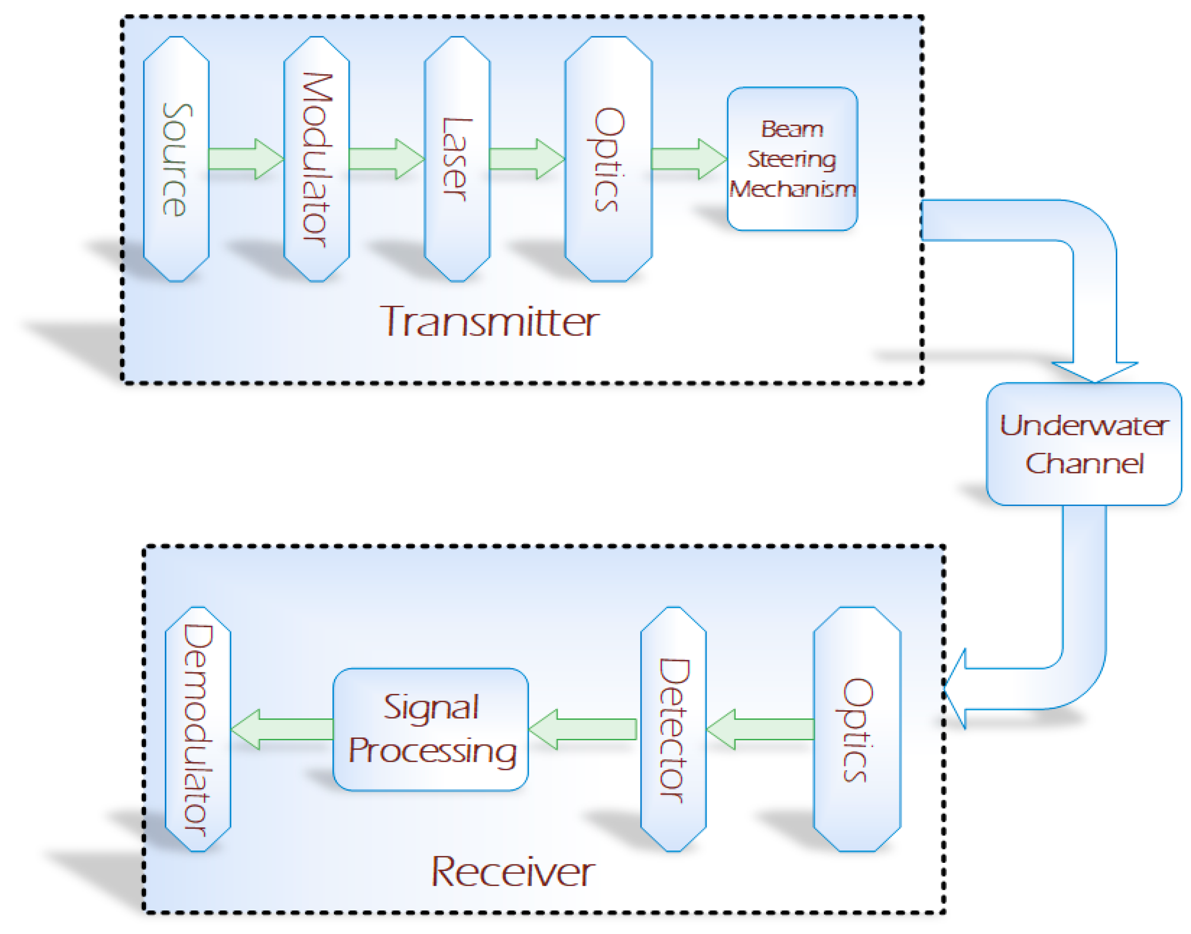
Communication system block diagram. The functional blocks at the transmitter are responsible for processing the input message encoding modulating and transmitting over the communication channel. Optical Source provides electrical to optical conversion can be LEDs on laser. This is the introductory video on Analog and Digital Communication.
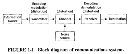
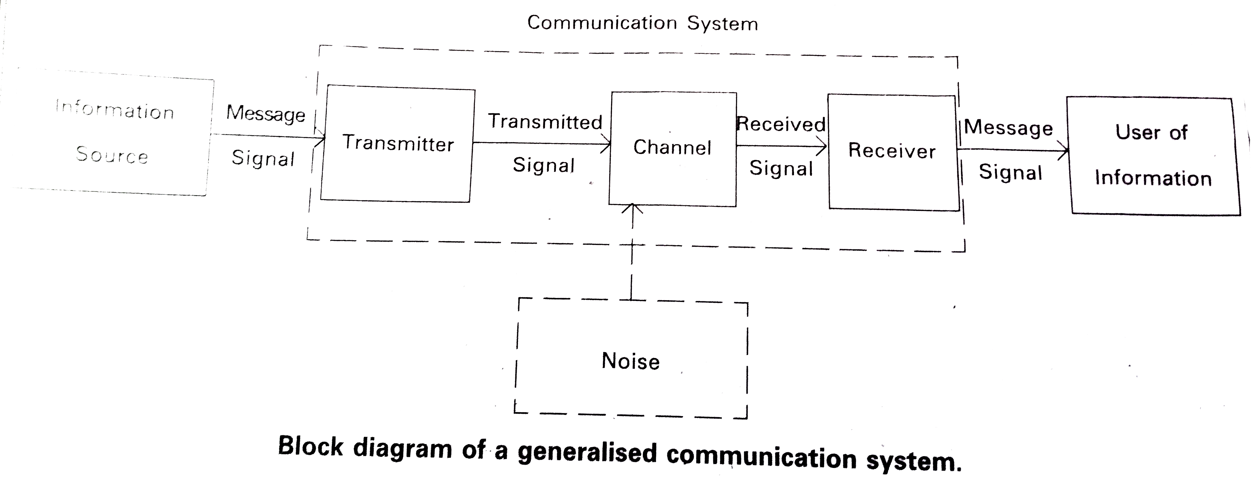
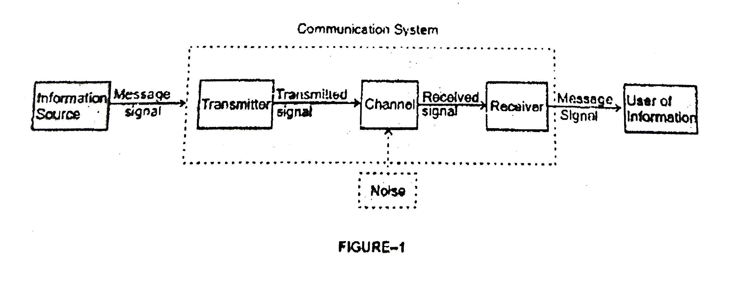
The essential components of a digital communication system are. I shows the block diagram of a general communication system in which the different functional elements are represented by blocks. Cable optical fiber free space Receiver.
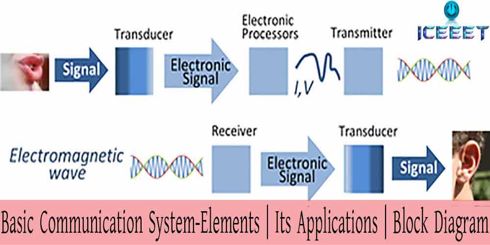
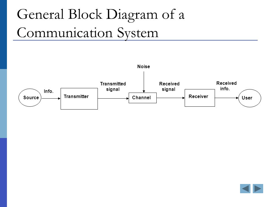
The information comes from the information source which originates it. Transducer amplifier modulator oscillator power amp antenna Channel. C K NaiduWatch the video lecture o.
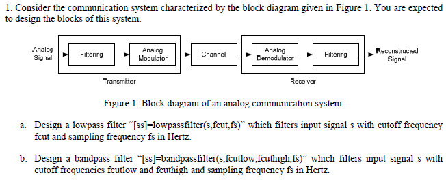
Lets consider in detail how this system works. Block diagrams are widely used by engineers for controls signal processing communications and mechatronics. Communications system block diagram In this general representation the channel might include an amplifier transmitting antenna propagation path a receiving antenna more amplifiers and a detector.
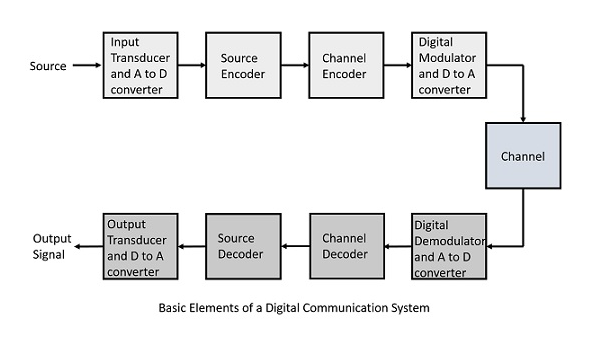
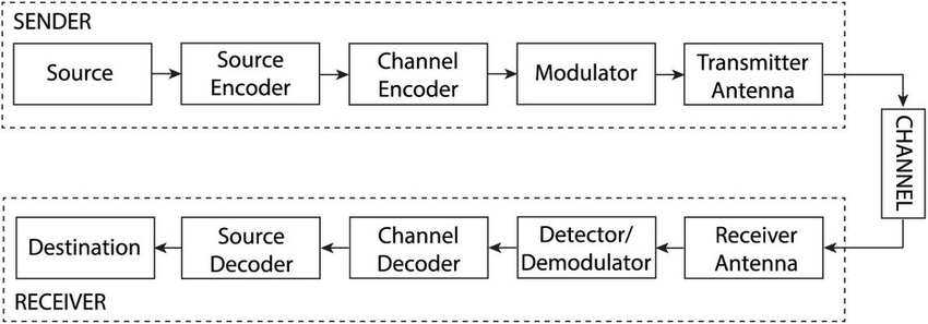
In this figure the different functional elements are represented by blocks. The source can be an analog signal. Following are the sections of the digital communication system.
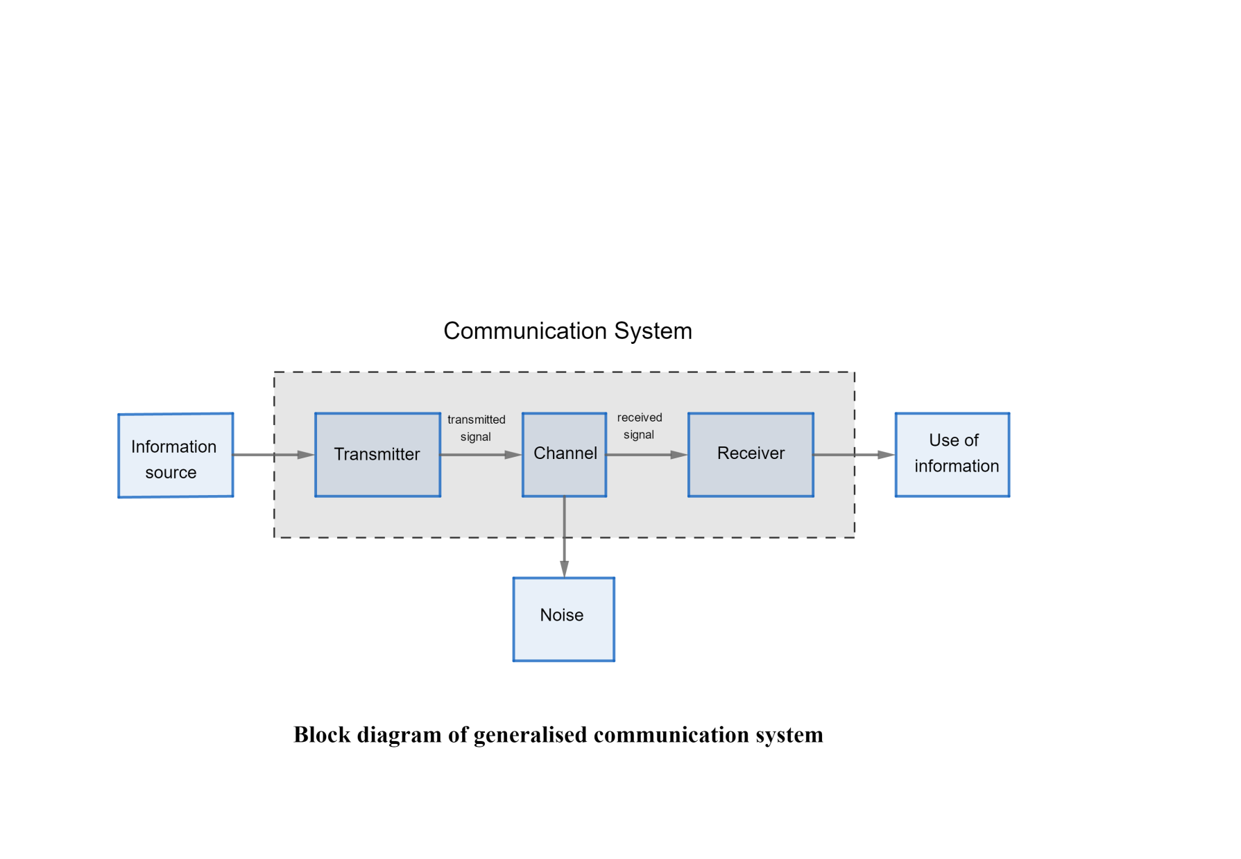
The block diagram of a communication system will have five blocks including the information source transmitter channel receiver and destination blocks. Need for Satellite Communication. Optical Fiber Communication System Block Diagram Electrical Transmitter contains electrical stage which drives an optical source to give modulation of light wave carrier.
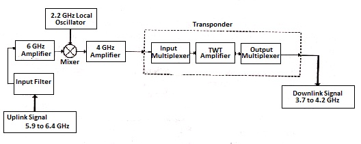
Satellite Communication System Block Diagram. A digital communication system consists of six basic blocks.
Lets consider in detail how this system works.
The block diagram of a communication system will have five blocks including the information source transmitter channel receiver and destination blocks. The uplink frequencies 59---64 GHZ are used for TN from the earth station to the satellite and down link frequencies 3742GHZ. A block diagram consists of blocks that represent different parts of a system and signal lines that define the relationship between the blocks. Satellite Communication Block Diagram. Block diagram of a simple Digital Communication System. Following are the sections of the digital communication system. Block Diagram of a Communications Satellite Doe Communications Payload Transponder Receiver Section Transponder Transmitter Section Telemetry Attitude Control Commanding Fuel Batteries Power SystemThermal System Propulsion System Solar Arrays Solar Arrays Down Converter Pre-Amplifier Filter High Power Amplifier Filter Rx Antennas Tx Antenna. Base-band processor Band-pass modulator 7. Basic block diagram of a communication system.
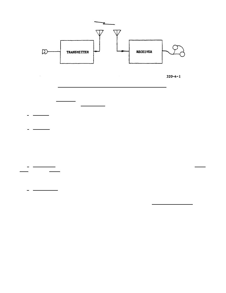
Cable optical fiber free space Receiver. Block Diagram of Digital Communication System. Satellite Communication System Block Diagram. Ground wave propagation and skywave propagation are the two ways in which communication took place for a certain distance. The information comes from the information source which originates it. Antenna amplifier demodulator oscillator power amplifier transducer Recipient. Base-band processor Band-pass modulator 7.
















Post a Comment for "Communication System Block Diagram"