Skip to content Skip to sidebar Skip to footer

Locomotive Air Brake System Schematic

Schematic Of Automatic Air Brake System Download Scientific Diagram

Schematic Of Automatic Air Brake System Download Scientific Diagram

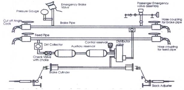
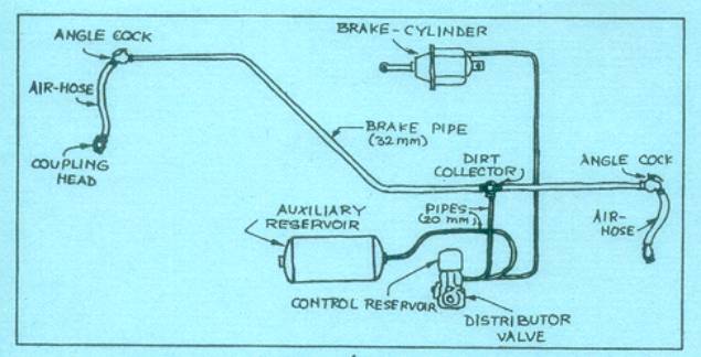
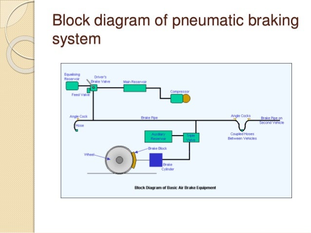
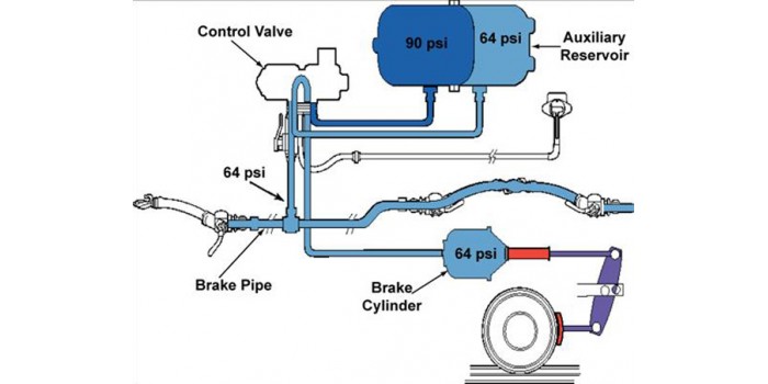
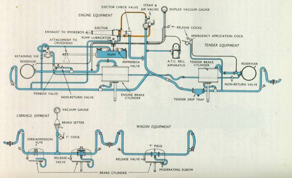
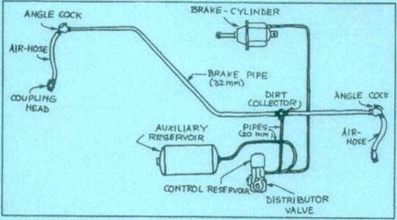
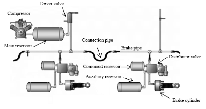
Locomotive air brake system schematic. A braking systems basic components include an air compressor and filtration device as shown by A5 in the schematic diagram in Figure 2 1 a main duct pneumatic suspension devices L1 a braking airline and control system B1 including a parking braking device B7 and a braking control section B13 main brakes C1 and electronic antiskid devices G1. Illustrates the schematic layout of air brake equipment on the. Single pipe air brake system Twin pipe air brake system A irr kbbraakee essyyssttemm suusseedd inn ffrreeiigghht ssttoocckk iiss siinnggllee piippee ggrra adduuaatteedd br reelleeassee aaiirr braakkee ssyyssteemmThe diagram shown on page 2.

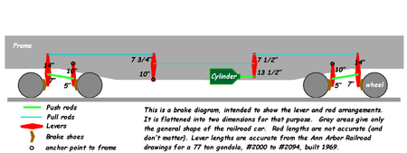
Pressurised air is used to move linkage which pushes Brake shoes against the moving wheel. It is purely compressed air brake system known as independent brake system. Locomotive brake of modern design which incorporates all of the operating features necessary for the control of freight and passenger train braking systems.

AIR BRAKES - Air brakes serve a multiple purpose for they can stop retard or hold locomotives or cars. Interruption of the flow of air to the brake pipe for purposes of break -in-two protection. Overview Features Benefits The CCB II computer controlled brake is a microcomputer network-based system that provides faster response for full automatic and independent brake control on freight and passenger locomotives.

31 LOCO BRAKE SYSTEM Introduction Loco brake system is provided to stop the Locomotive whenever it runs as light engine. Here is a simplified schematic of a train braking syst. Air brake system is classified as.

Sat 11th Jun 2011 534pm. Where the pressure of the reservoir reaches the maximum degree. Hence air brake cylinders can be a lot smaller for the same pull or push.

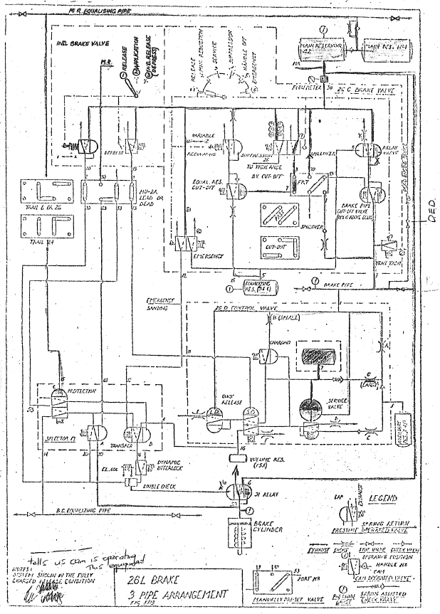
26-l brake equipment for locomotives. It can apply the brake release it or hold it on after a partial application. Of an Air Brake System Section 5Trailer System 3711 The Components of an Air Brake System 12 Compressor and Governor 12 Reservoirs 14 Air Dryer 15 Safety Valve 16 Foot Valve 16 Brake Chambers Slack Adjusters and Brake Lining 16 Wedge Brakes 20 Disc Brakes 21 AirOverHydraulic Brake Systems 21 AirActuatedHydraulic Brake System 21.

As shown in figure. Locomotives Brakes can be applied and released through independent brake valve SA9 independently.

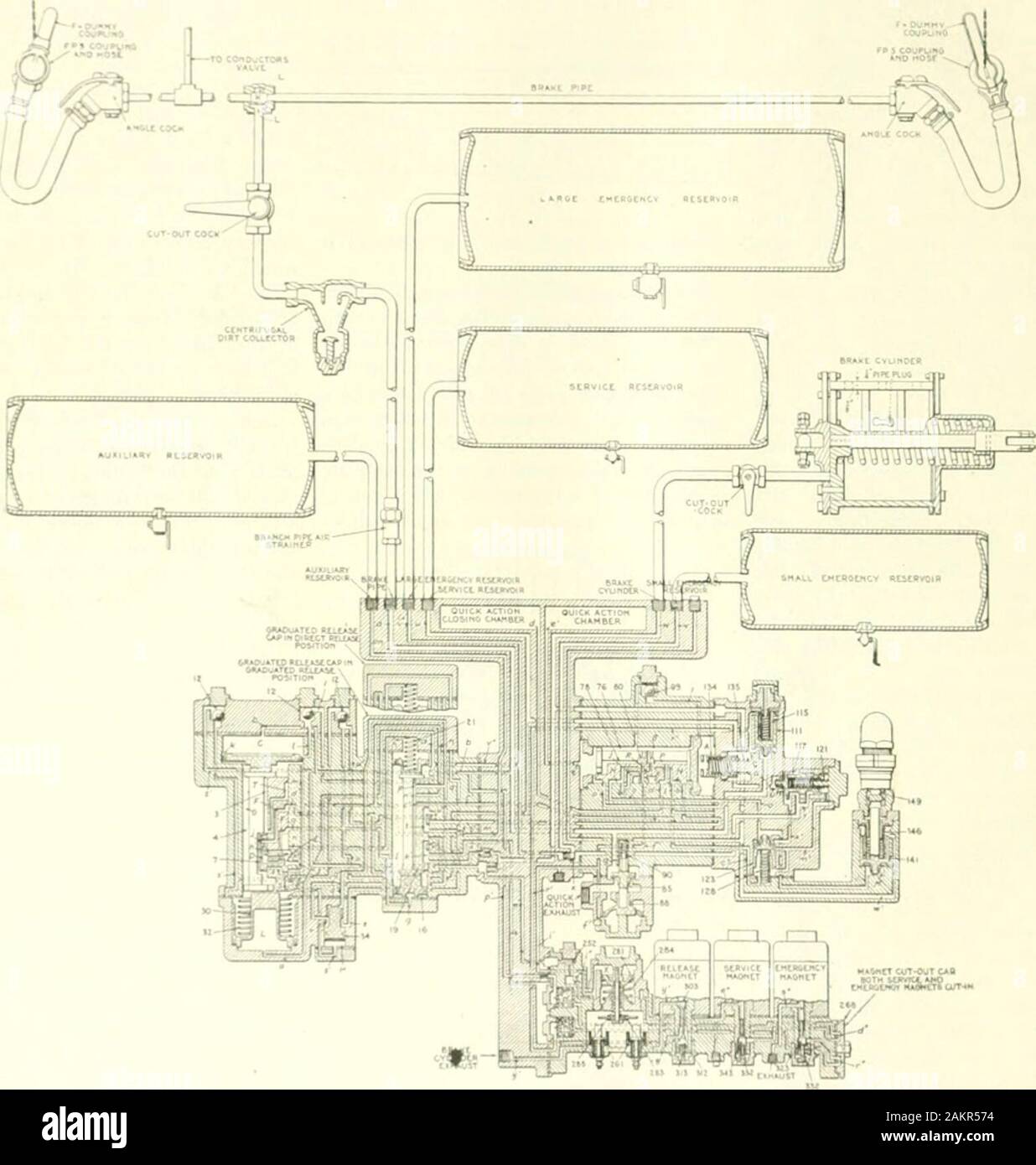
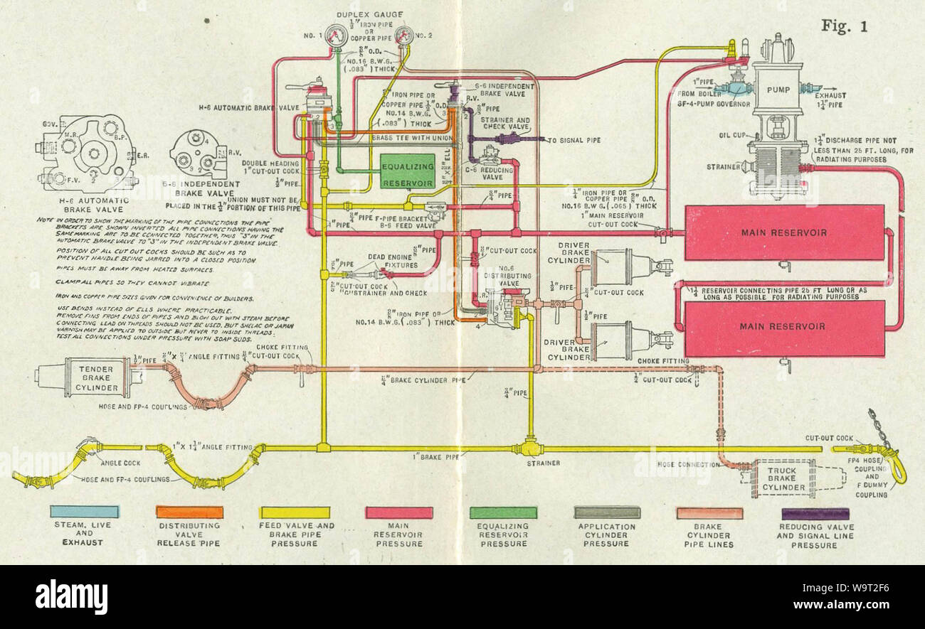
Piping Diagram From 1909 Of A Westinghouse 6 Et Air Brake System On A Locomotive Stock Photo Alamy

Piping Diagram From 1909 Of A Westinghouse 6 Et Air Brake System On A Locomotive Stock Photo Alamy

Schematic Diagram Of The Train Air Brake Download Scientific Diagram

Schematic Diagram Of The Train Air Brake Download Scientific Diagram

Brakes The Railway Technical Website Prc Rail Consulting Ltd

Brakes The Railway Technical Website Prc Rail Consulting Ltd

A9 Air Brake System To Train Formation From Locomotive Animated Video Air Brake Brake System Locomotive

A9 Air Brake System To Train Formation From Locomotive Animated Video Air Brake Brake System Locomotive

Rail Maniac Air Brake System I R

Rail Maniac Air Brake System I R

Locomotive Air Brake System Diagram Quizlet

Locomotive Air Brake System Diagram Quizlet

Irfca Brake Systems Used By Ir

Irfca Brake Systems Used By Ir

Brakes The Railway Technical Website Prc Rail Consulting Ltd

Brakes The Railway Technical Website Prc Rail Consulting Ltd

Components In The Locomotive Air Brake System Diagram Quizlet

Components In The Locomotive Air Brake System Diagram Quizlet

Coals To Newcastle Physics Train Brakes

Coals To Newcastle Physics Train Brakes

Irfca Brake Systems Used By Ir

Irfca Brake Systems Used By Ir

A Train Air Brake Force Model Locomotive Automatic Brake Valve And Brake Pipe Flow Formulations Semantic Scholar

A Train Air Brake Force Model Locomotive Automatic Brake Valve And Brake Pipe Flow Formulations Semantic Scholar

Railway Air Brake Youtube

Railway Air Brake Youtube

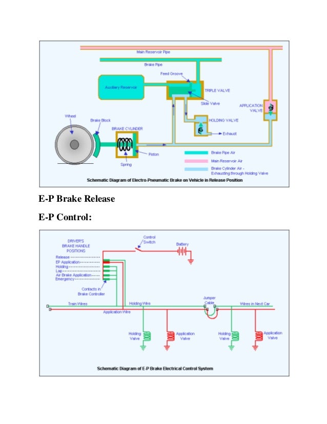
Electro Pneumatic Brakes The Railway Technical Website Prc Rail Consulting Ltd

Electro Pneumatic Brakes The Railway Technical Website Prc Rail Consulting Ltd

Tsb Laboratory Report Lp187 2013 Transportation Safety Board

Tsb Laboratory Report Lp187 2013 Transportation Safety Board

Railway Wagon Breaking System

Railway Wagon Breaking System

An Investigation On Braking Systems Used In Railway Vehicles Sciencedirect

An Investigation On Braking Systems Used In Railway Vehicles Sciencedirect

Rdso Indianrailways Gov In

Rdso Indianrailways Gov In

Railway Air Brake Wikipedia

Railway Air Brake Wikipedia

Schematic Diagram For The Electro Pneumatic Brake Control 29 Download Scientific Diagram

Schematic Diagram For The Electro Pneumatic Brake Control 29 Download Scientific Diagram

How A Train S Air Brakes Works

How A Train S Air Brakes Works

South Devon Railway Brake Cylinder

South Devon Railway Brake Cylinder

Electro Pneaumatic Breaking System

Electro Pneaumatic Breaking System

3

3

Railway Air Brake Wiki Thereaderwiki

Railway Air Brake Wiki Thereaderwiki

Air Brake System Of Indian Railways Seminar Report Ppt Pdf For Mechanical

Air Brake System Of Indian Railways Seminar Report Ppt Pdf For Mechanical

Tech Stuff Boomerdownunder

Tech Stuff Boomerdownunder

Railway Air Brake Systems Youtube

Railway Air Brake Systems Youtube

Rdso Indianrailways Gov In

Rdso Indianrailways Gov In

Air Brake System Pdf Brake Vehicle Parts

Air Brake System Pdf Brake Vehicle Parts

Number 26l Brake Stand Train Decor Railroad Photography Railroad Art

Number 26l Brake Stand Train Decor Railroad Photography Railroad Art

Railway And Locomotive Engineering Ementsbrakes For Passenger Cars Some Months Ago F Slated That Acomplete Description Of The Constructionand Operation Of The U C Universalcontrol Passenger Car Brake Equipmentwould Be Printed

Railway And Locomotive Engineering Ementsbrakes For Passenger Cars Some Months Ago F Slated That Acomplete Description Of The Constructionand Operation Of The U C Universalcontrol Passenger Car Brake Equipmentwould Be Printed

Of Brake Stands And Piping

Of Brake Stands And Piping

How Steam Engines Work

How Steam Engines Work

File A Textbook On The Locomotive And The Air Brake 1901 14572318498 Jpg Wikimedia Commons

File A Textbook On The Locomotive And The Air Brake 1901 14572318498 Jpg Wikimedia Commons

Aires Cerebrales Def

Aires Cerebrales Def

Air Brake System Parts Working Diagram Principle Advantages

Air Brake System Parts Working Diagram Principle Advantages

Tech Stuff Boomerdownunder

Tech Stuff Boomerdownunder

Westinghouse Air Brakes G Scale Model Train Forum

Westinghouse Air Brakes G Scale Model Train Forum

Nyab Com

Nyab Com

Brakes The Maine On2 Faq

Brakes The Maine On2 Faq

What Is The Use Of The Lap Position On A Train Brake Lever Quora

What Is The Use Of The Lap Position On A Train Brake Lever Quora

Locomotive Engine Running And Management The Westinghouse Air Brake

Locomotive Engine Running And Management The Westinghouse Air Brake

Nyab Com

Nyab Com

Westinghouse And The Fail Safe Train Air Brake Part 1 The Problem Electrical Engineering News And Products

Westinghouse And The Fail Safe Train Air Brake Part 1 The Problem Electrical Engineering News And Products

File A Textbook On The Locomotive And The Air Brake 1901 14735985376 Jpg Wikimedia Commons

File A Textbook On The Locomotive And The Air Brake 1901 14735985376 Jpg Wikimedia Commons

Stopping The Train Railway Wonders Of The World

Stopping The Train Railway Wonders Of The World

Image From Page 86 Of Railway And Locomotive Engineering Flickr

Image From Page 86 Of Railway And Locomotive Engineering Flickr

Air

Air

The diagram of air brake system shown below which.

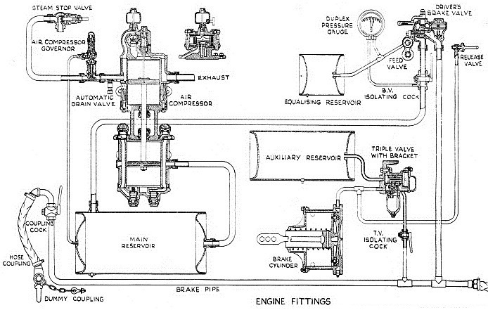
The air is drawn into a compressor and stored in a main reservoir at 7-10 bar 100-140 lbssqin. Illustrates the schematic layout of air brake equipment on the. Locomotives Brakes can be applied and released through independent brake valve SA9 independently. Its pretty neat -Id been wishing for something similar on-line so a user could see how a real air brake system operates at various points in the locomotives air system and the trainline - although it wont be confused with the MicroSoft Train Simulator or other sophisticated application or simulation software. In the air brakes simplest form called the straight air system compressed air pushes on a piston in a cylinder. 26-l brake equipment for locomotives. AIR BRAKES - Air brakes serve a multiple purpose for they can stop retard or hold locomotives or cars. Here is a simplified schematic of a train braking syst. SALIENT FEATURES OF IRAB 1 SYSTEM 1.


If you are stuck for space to mount the brake cylinder stick with air you can use up to 50 psi or so whereas vacuum is generally limited to the difference between atmospheric and the vacuum in your system normally 12 - 13 psi. It takes air from the atmosphere compresses it and delivers to the air reservoir through an un-loader valve. There are limitations in their use for holding purposes and they will be covered later in this manual. 31 LOCO BRAKE SYSTEM Introduction Loco brake system is provided to stop the Locomotive whenever it runs as light engine. The piston is connected through mechanical linkage to brake shoes that can rub on the train wheels using the resulting friction to slow the train. Air brake system is classified as. This equip ment employs as the major components a 26-C Brake Valve.
Post a Comment for "Locomotive Air Brake System Schematic"